NEPI Engine – Navigation Systems
Introduction
This tutorial covers configuring and connecting navigation and positioning (NavPose) hardware systems for NEPI NPX driver supported data sources. The NEPI NPX driver abstraction layer provides plug and play integration and common API interface for all connected navigation and positioning systems, regardless of their native interface, making data manipulation, data geo tagging, and automation processes easy to build, maintain, and reuse across all types of solution platforms.
NEPI NavPose Conventions
NEPI uses a north-east-down (NED) global reference frame and a forward-right-down (FRD) local body reference frame as defined below.
NED Global Frame: X is North, Y is East, Z is Down (Towards Earth Center), and Yaw 0 degrees faces North and rotates positive using right hand rule around Z axis down.
Local Body Frame (Fixed to Robotic Platform Body): X axis points in Forward (defined by geometry and not by movement) direction (RHR roll axis), Y axis points to the Left (geometrically) (RHR pitch axis), Z axis points Up (geometrically) (RHR yaw axis), Yaw 0 degrees faces X and rotates positive using right hand rule around Z axis down.
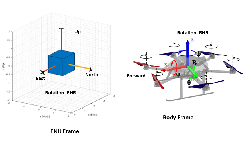
NOTE: NEPI’s “nepi_nav.py” utility module includes a python utility package for converting between NavPose frames and reference formats. You can import the module from “nepi_edge_sdk_base” folder.
Fixed NavPose Solutions
In this section, we will cover setting up a fixed NEPI NavPose solution. This is useful for configuring a NEPI NavPose solution for a fixed smart sensor device, or initializing the NavPose solution for pan and tilt or mobile robotic system on startup.
NOTE: If you want these values to persist on startup, you will need to use the “navpose_set_fixed_config_script” NEPI automation script set to “Auto Start”.
What you will need
1) 1x NEPI-enabled device with internet access. This tutorial uses an edge-compute processor box that includes an NVIDIA Jetson Xavier NX embedded GPU module with NEPI Engine software installed.
NOTE: See available off-the-shelf NEPI enabled edge-compute options at: https://numurus.com/products-nepi-enabled-hardware/
2) 1x PC with internet access and configured to access the NEPI device’s RUI browser-based interface and user storage drive. This tutorial uses a Windows 11 PC and a USB GigE Ethernet adapter and Ethernet cable.
Instructions
1) Connect the NEPI device to your PC’s Ethernet adapter using an Ethernet cable, then power your NEPI device.
NOTE: Instructions for configuration a PC and connecting to a NEPI device’s RUI and user storage drive are provided in the NEPI Engine Getting Started tutorial at: https://nepi.com/nepi-tutorials/nepi-engine-connecting-and-setup/
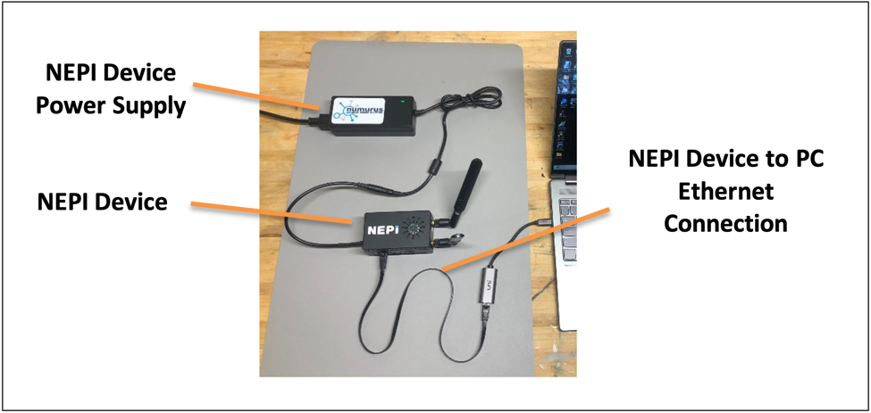
2) Open your NEPI device’s RUI SENSOR/NAVPOSE tab and enter any fixed values you want to use into the NAV/POSE SETUP section. Be sure not to hit enter until all values in red are updated to the new values you want.
NOTE: The values will turn back to all zeros after hitting enter.

3) In the NAV/POSE OUTPUT section of this RUI tab, click the “Reinitialize” button, and you should see the values you entered show up in the indicator boxes.
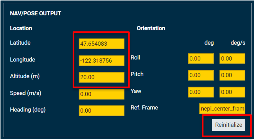
4) If you want to save these settings, go to the RUI’s SYSTEM/ADMIN tab and select the “Save” button. Alternatively, you can set these controls with an automation script like the “navpose_set_fixed_config_script.py” script available in the NEPI sample automation scripts GitHub repo at: https://github.com/numurus-nepi/nepi_sample_auto_scripts
NEMA Hardware
In this section, we will show how to connect a GPS NMEA navigation data stream and configure the NEPI NavPose solution to use it.
What you will need
1) 1x NEPI-enabled device with internet access. This tutorial uses an edge-compute processor box that includes an NVIDIA Jetson Xavier NX embedded GPU module with NEPI Engine software installed.
2) 1x PC with internet access and configured to access the NEPI device’s RUI browser-based interface and user storage drive. This tutorial uses a Windows 11 PC and a USB GigE Ethernet adapter and Ethernet cable.
3) 1x NEPI NDX supported GPS sensor or simulator. This tutorial uses the free nmeasimulator GPS simulator available from: https://github.com/panaaj/nmeasimulator/releases
Instructions
1) Connect the NEPI device to your PC’s Ethernet adapter using an Ethernet cable, then power your NEPI device.
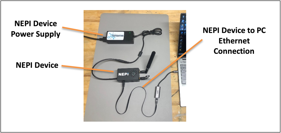
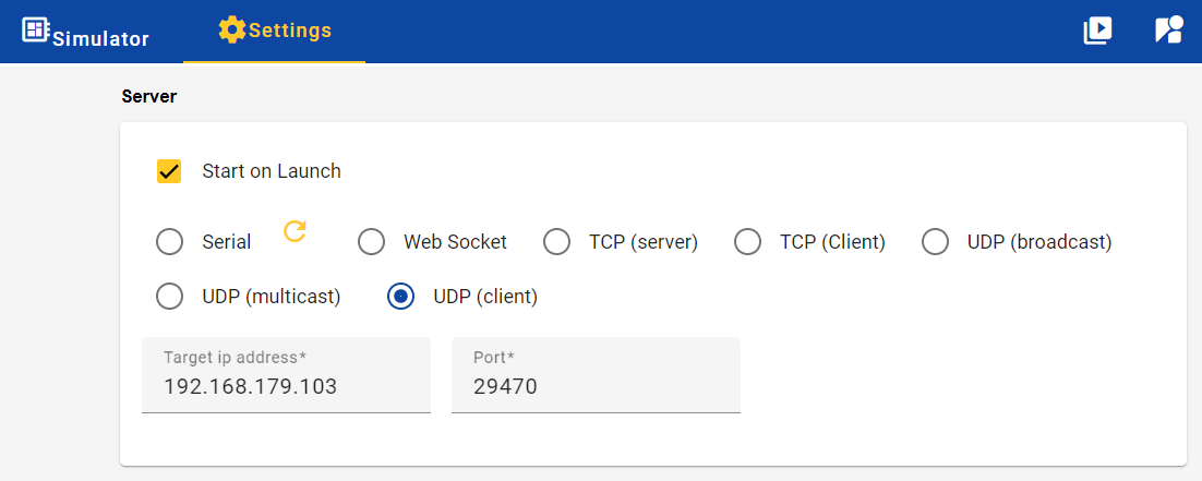
2) Start the nmeasimulator application on your PC and click the settings top menu options. Enter the following settings:
Start on Launch: Checked
Comms Option: UDP (client)
Target ip address: 192.168.179.103
Port: 29470
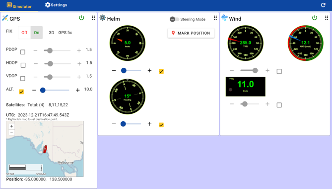
3) Select the “Simulator” top menu option and configure your NMEA simulation values.
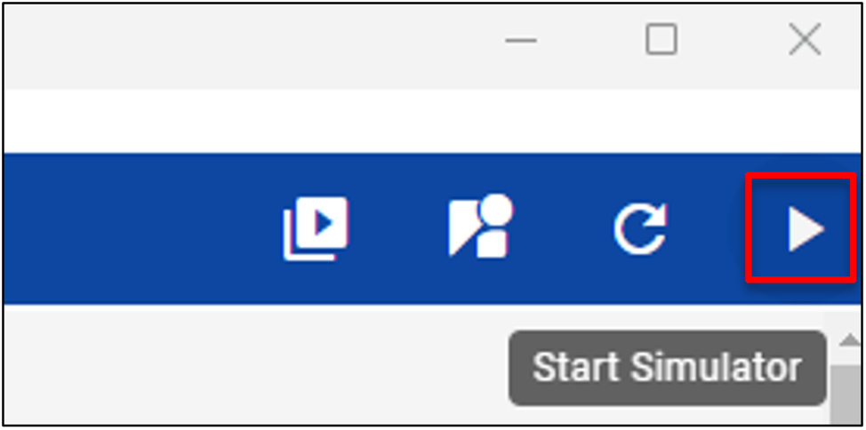
4) Click the play button in the top menu on the far right.
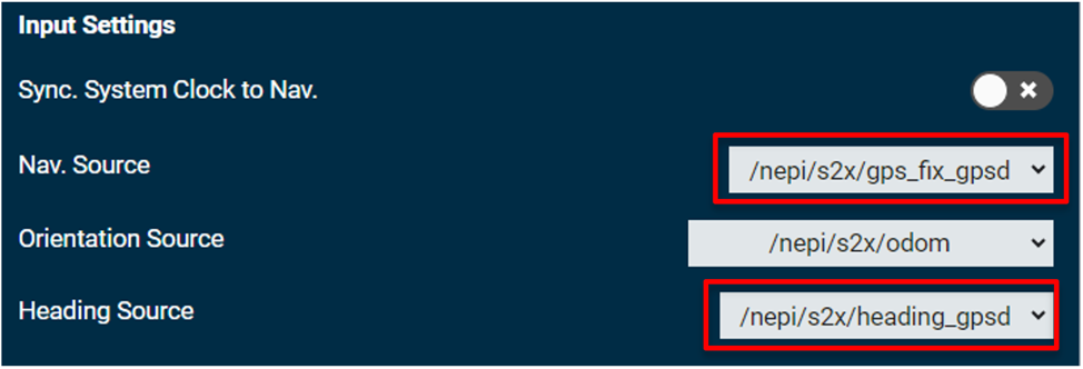
5) Open your NEPI device’s RUI SENSORS/NAVPOSE tab and select the new GPS and heading topics now available from the simulated GPS NMEA stream you just created in the “Input Settings” box.
6) In the NAV/POSE OUTPUT section of this RUI tab, you should see the GPS and heading values updating from your GPS streams.
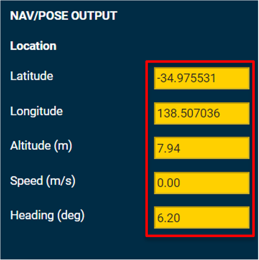
7) If you want to save these settings, go to the RUI’s SYSTEM/ADMIN tab and select the “Save” button. Alternatively, you can set these controls with an automation script like the “navpose_config_script.py” script available in the NEPI sample automation scripts GitHub repo at: https://github.com/numurus-nepi/nepi_sample_auto_scripts
Camera, PanTIlt, & Robotic Hardware
In this section, we will show how to configure the NEPI NavPose system to use NavPose data streams from a connected NEPI IDX camera, PTX pantilt, or RBX robotic control system. All three NEPI driver groups have an option to publish Navigation, Orientation, and/or Heading data streams if the specific hardware component produces such data.
What you will need
1) 1x NEPI-enabled device with internet access. This tutorial uses an edge-compute processor box that includes an NVIDIA Jetson Xavier NX embedded GPU module with NEPI Engine software installed.
2) 1x PC with internet access and configured to access the NEPI device’s RUI browser-based interface and user storage drive. This tutorial uses a Windows 11 PC and a USB GigE Ethernet adapter and Ethernet cable.
3) 1x NEPI IDX camera, PTX pantilt, or RBX robotic control system with navigation, orientation, and/or heading data output capabilities. This tutorial uses Pixhawk PX4 autopilot module with a built-in IMU sensor, external GPS receiver, and ardupilot firmware configured for MAVLink data streaming on its TELEM 2 port.
NOTE: For details on configuring and connecting an ardupilot enabled autopilot module, see the NEPI Engine – Hardware Interfacing – Robotic Control Systems tutorial at: https://nepi.com/tutorials/
Instructions
1) Connect the NEPI device to the MAVLink configured Pixhawk autopilot system’s TELEM 2 port using a Pixhawk TELEM to USB cable, then power the NEPI device and Pixhawk autopilot systems.
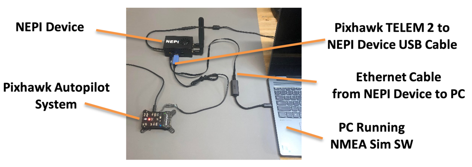
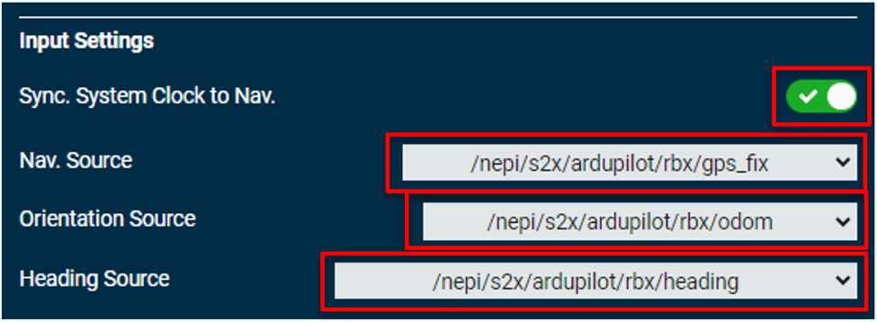
2) Open your NEPI device’s RUI SENSORS/NAVPOSE tab and select any GPS, orientation, and heading topics for your “idx”, “ptx”, or “rbx” connected hardware component. Search the dropdown boxes under the “Input Settings” pane for your component under each of the fields. If your hardware supports that type of data output, you will see an option listed. For the Pixhawk system connected we have all three data streams available that we can connect to listed under the “ardupilot/rbx” driver’s namespace. You also have the option of syncing the NEPI clock with the Nav Source Clock usually set by a GPS message.
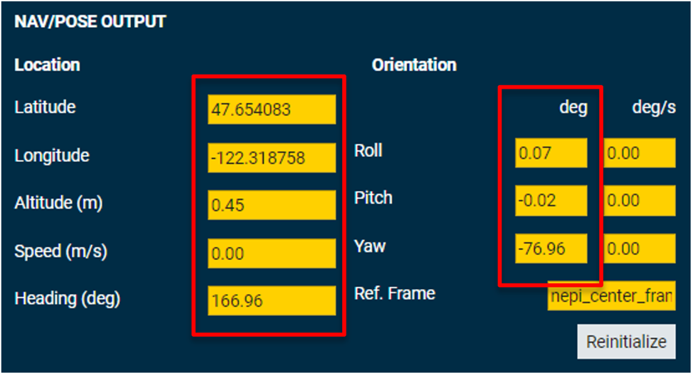
3) In the NAV/POSE OUTPUT section of this RUI tab, you should see the GPS, heading, and orientation values updating as you move the Pixhawk system around.
4) If you want to save these settings, go to the RUI’s SYSTEM/ADMIN tab and select the “Save” button. Alternatively, you can set these controls with an automation script like the “navpose_config_script.py” script available in the NEPI sample automation scripts GitHub repo at: https://github.com/numurus-nepi/nepi_sample_auto_scripts
Setting NavPose Source Offsets
NEPI’s NavPose management system supports adding offset values for externally connected NavPose source hardware systems. Offset values can be set in the NEPI device’s RUI Sensors/NavPose page under the “IMU/AHRS Offsets” pane, or programmatically using an automation script.
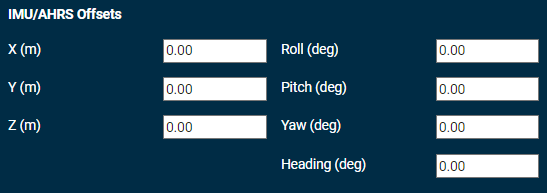
All offsets should be applied positive or negative depending on which direction you are moving in the pipeline relative to the data. For instance, sensor data moving to a common reference frame should be negative measured from the device frame of reference, while external frame of references should be positive measured from the device frame of reference. The transform values must be calculated based on the following directions and order of transformation:
1) First Sync INS and NEPI clocks using external NTP Server
2) Open the RUI SENSORS/NAVPOSE tab and select the appropriate data sources from the dropdown boxes in the NavPose Input Settings section
3) Apply any transforms required using the following conventions:
4) Transforms are positive FROM the Device Frame of Reference TO the External INS Frame of Reference
5) Transformation order is X, Y, then Z in meters
6) Rotation order is ∆X, then ∆Y, then ∆Z in degrees (right-handed rotations) where the rotation axes are fixed to DFoR throughout the rotation sequence
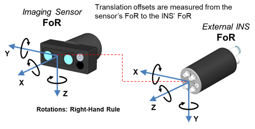
For the example above, the correct offsets for this configuration as measured from the Sensor to INS Offsets are: X= –0.25, Y= 0.007, Z= 0.152 ∆X=90.0, ∆Y=0.0, ∆Z=90.0

