NEPI Engine – Ardupilot Control Systems
Introduction
This tutorial will show you how to connect and control a robotic platform running Ardupilot autopilot software using the NEPI ROS integrated MAVLink interface (Mavros), NEPI NavPose Management System, and NEPI Automation Script Management System. This tutorial uses a Pixhawk PX4 control board configured with Ardupilot software.
Position and Orientation Frame Conventions
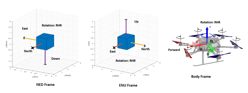
Ardupilot and MAVLink use a north, east, down (NED) reference frame, NEPI, ROS, and mavros use an east, north, up (ENU) reference frame. Almost all of the mavros interfaces expect ENU pose data and convert to NED internally before sending actual MAVLink messages.
ENU Frame: X is East, Y is North, Z is Up (Away from Earth Center), and Yaw 0 degrees faces East and rotates positive using right hand rule around Z axis up.
NED Frame: X is North, Y is East, Z is Down (Towards Earth Center), and Yaw 0 degrees faces North and rotates positive using right hand rule around Z axis down.
There is also a body fixed frame used for describing relative offsets from current location,
Local Body Frame (Fixed to Robotic Platform Body): X axis points in Forward (defined by geometry and not by movement) direction (RHR roll axis), Y axis points to the Left (geometrically) (RHR pitch axis), Z axis points Up (geometrically) (RHR yaw axis), Yaw 0 degrees faces X and rotates positive using right hand rule around Z axis down.
NOTE: NEPI’s “nepi_nav.py” utility module includes a python utility package for converting between NavPose frames and reference formats. You can import the module from “nepi_edge_sdk_base” folder.
Global Altitude Frame Conventions
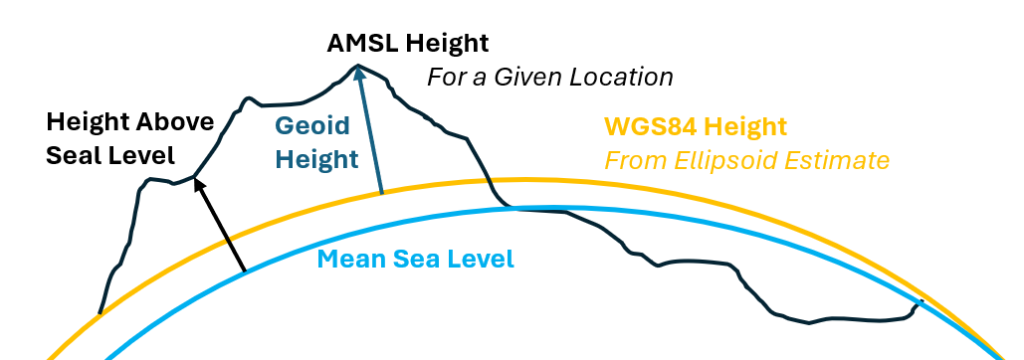
Two common altitude standards used for presenting robotic altitude are:
AMSL – Average meters above mean sea level of earth’s surface at a given location.
WGS84 – Ellipsoid surface estimate of earth’s surface at a given location.
You can convert between the two altitudes references by adding or sub-tracking the Geoid Height value for the current Latitude and Longitude location:
AMSL = WGS84 + Geoid_Height
You can find the Geoid Height for you current Lat Long global location using this link: https://geodesy.noaa.gov/GEOID/GEOID18/computation.html
NOTE: NEPI includes a python utility package for converting between NavPose frames and reference formats. To access NEPI’s NavPose utility library, see the “nepi_navpose.py” file in the “resources” of the NEPI Sample Automation Scripts GitHub code repository at:
https://github.com/numurus-nepi/nepi_sample_auto_scripts
Online documentation on which standards different software packages and hardware devices use is ambiguous, confusing, and in some cases wrong. The table below defines the assumed standards for NEPI NavPose, NEPI RBX Drivers, GPS, Ardupilot Firmware, MAVLink Interface, and MAVROS Python Module, followed by some experimental validation.
Altitude Convention Table
| Software or Device | Input | Output | Note |
| GPS | N/A | WGS84 | |
| NEPI NavPose System | WGS84 | WGS84 | |
| NEPI RBX Drivers | See Note | See Note | NEPI RBX drivers received and send messages to robotic devices in their native, or required, altitude standard(s). Internally RBX drivers use WGS84 altitude. |
| Ardupilot Firmware | WGS84 | WGS84 | |
| MAVLink Interface | WGS84 | WGS84 | |
| MAVROS Python Module | AMSL** | WGS84 | ** Based on experimentation. Does not match with other MAVROS documentation sources. |
Altitude Assumptions Validation
To validate the altitude assumptions in the table above, we will follow altitude data from beginning to end during an NEPI automation process. The table shows the results and the value recorded. The following location was used for the test:
latitude: 47.6540828
longitude: -122.3187578
Which has a Geoid Height at that location of:
geoid height: -22.43
Altitude Convention Validation Table
| Process Test Below. Results at Different Points in System to Right | ROS / MAROS | MAVLink / Ardupilot |
| NEPI publishes fake WSG84 GPS message to MAVROS “hil/gps” ROS topic | (o) WGS84 | (o) WGS84 |
| Ardupilot GPS data is published on MAVLink interface, then MAVROS to ROS on MAVROS “/global_position/global” ROS topic | (-22.43) AMSL | (o) WGS84 |
| NEPI RBX driver converts the MAVROS GPS to WGS84 before publishing to NEPI NavPose system | (o) WGS84 | N/A |
| NEPI RBX driver receives a 40 meter WGS84 altitude got0 global position command on NEPI RBX “/rbx/goto_location” ROS topic | (40) WGS84 | N/A |
| NEPI RBX driver sends AMSL altitude goto setpoint command on MAVROS “/position/global” ROS topic | (40) WGS84 | (40) WGS84 |
Useful References
a. NEPI Engine: https://numurus.com/library/
b. API Manual – NEPI Engine – Local System Interfacing: https://numurus.com/library/
c. MAVLink Interface information: https://ardupilot.org/dev/docs/mavlink-commands.html
d. Pixhawk Guide – MAVLink Messaging: https://dev.px4.io/v1.11_noredirect/en/middleware/mavlink.html
What you will need
1) 1x NEPI-enabled device. This tutorial uses an edge-compute processor box that includes an NVIDIA Jetson Xavier NX embedded GPU module with NEPI Engine software installed.
NOTE: See available off-the-shelf NEPI enabled edge-compute options at: https://numurus.com/products-nepi-enabled-hardware/
2) 1x PC with internet access and configured to access the NEPI device’s RUI browser-based interface and user storage drive. This tutorial uses a Windows 11 PC and a USB GigE Ethernet adapter and Ethernet cable.
NOTE: Instructions for configuration a PC and connecting to a NEPI device’s RUI and user storage drive are provided in the NEPI Engine Getting Started tutorials at:
https://nepi.com/nepi-tutorials/nepi-engine-connecting-and-setup/
https://nepi.com/nepi-tutorials/nepi-engine-user-storage-drive/
3) 1x Pixhawk autopilot system (This tutorial uses a Pixhawk px4)
4) 1x (Optional) Quadcopter drone platform and GPS (This tutorial uses a HAWK’S WORK F450 Drone Kit)
5) 1x NEPI IDX supported 2D camera (This tutorial uses a USB webcam mounted on the drone)
6) 1x Micro USB to USB A cable for connecting your Pixhawk to your PC
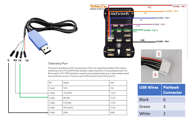
7) 1x Pixhawk TELEM to NEPI-Device adapter cable. This could be a USB to Pixhawk or UART Pin to Pixhawk adapter cable.
This tutorial assumes you are using a USB to Adapter Cable. You can purchase one from Numurus (part number 101076-00) or build your own using the diagram and table in the image below.
NOTE: NEPI’s MAVLink autodiscovery system will check any connnected (USB or UART direct) connections for a connected MAVLink system.
Hardware Setup
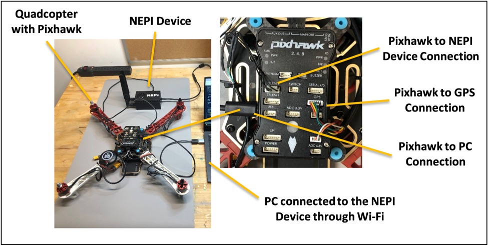
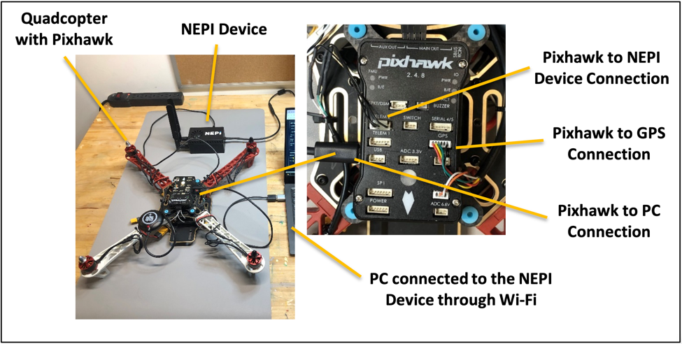
1) Connect your NEPI-enabled device to the Pixhawk’s TELEM1 (or TELEM2) port using the USB to Serial Pixhawk adapter cable. Plug your GPS module into the Pixhawk’s GPS1 port.
2) Power on all devices
3) Connect your PC to your NEPI device through a wired Ethernet connection or a NEPI Wi-Fi access point you have configured on your NEPI device.
Configuring Your Autopilot System
This document assumes your Pixhawk autopilot system is running ardupilot firmware, or some variation. It assumes you have installed and connected your Pixhawk system to a PC running the Mission Planner software available at: https://ardupilot.org/planner/docs/mission-planner-installation.html
NOTE: You can download the Pixhawk ardupilot configuration file used in the interfacing portion of this document, along with the NEPI ardupilot driver and automation scripts demonstrated from: https://www.dropbox.com/scl/fo/0v4geo9n7pn25zvgeyppb/h?rlkey=ix089itzrai1huruv27dvutuy&dl=0
Initial Firmware setup
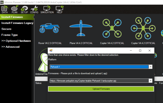
1) Select the SETUP/Install Firmware menu item and configure your system. For this tutorial, we installed Arducopter firmware option as shown below. There is a video tutorial at: https://youtu.be/uH2iCRA9G7k?si=_2uCsv3WCL6pa15U
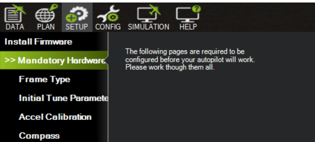
2) Next, perform all mandatory calibrations found under the Setup/Mandatory Hardware menu
3) Navigate to the CONFIG/Full Parameter Tree and set the Frame Class to 1 (Quad)
FRAME_CLASS = 1
BARO_OPTION = 1 (This was required for proper barometer reading from chip)
4) Click the “Write Params” button on the right sidebar to save settings, then power cycle your autopilot.
Drone Motor Setup
If you are testing without motors attached, skip this section.
1) Configure your drone motors as described below. These instructions are adopted from: https://ardupilot.org/copter/docs/connect-escs-and-motors.html
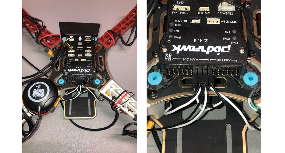
The diagram below shows motor order for each frame type. The numbers indicate which output pin from the autopilot should be connected to each motor/propeller. The propeller direction is shown in green (clockwise, CW) or blue (counterclockwise, CCW)
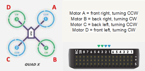
Example: Here us a photo of the motor configuration for our demonstration Pixhawk quadcopter setup.
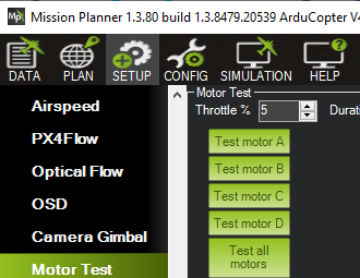
2) Test your motor configuration from within the Mission Planner software by selecting the SETUP/Optional Hardware/Motor Test option and clicking each of the “Test motor” A thru D buttons. Verify proper motor letter assignment and spin direction against the graphic above.
If you are having difficulties setting up your motors, this link provides some useful guidance: https://discuss.ardupilot.org/t/my-method-for-iteratively-configuring-motor-ordering-and-direction/67644
3) For development purposes you may wish to reduce motor spin speed when armed from the CONFIG/Full Parameter Tree list:
MOT_PWM_MAX = 1500
MOT_SPIN_ARM = 0.03
MOT_SPIN_MAX = 0.5
MOT_SPIN_MIN = 0.15
Then Run the ESC Calibration in Mission Planner under SETUP/Mandatory Hardware menu.
MAVLink Fake GPS and Altitude Configuration
If you are working in a location that does not have GPS signals and want to use the mavros Fake GPS Simulator referenced later in this tutorial, you will need to configure your autopilot to use MAVLink supplied GPS data and GPS altitude data by setting the following parameter in the Mission Planning software’s CONFIG/Full Parameter Tree window/
AHRS_GPS_USE = 2
AHRS_COMP_BETA = 0.001
GPS_TYPE = 14
GPS_RATE_MS = 50
GPS_NAVFILTER = 0
EK3_ALT_M_NSE = 100
EK3_GPS_CHECK = 0
EK3_SRC_OPTIONS = 0
EK3_SRC1_POSXY = 3
EK3_SRC1_POSZ = 3
EK3_SRC1_VELXY = 3
EK3_SRC1_VELZ = 3
EK3_SRC1_YAW = 1
EK3_SRC2_POSZ = 3
EK3_SRC2_POSZ = 3
Select the “Write Params” option from the right sidebar menu to save your settings, then power cycle the Pixhawk autopilot system. After reconnecting to your autopilot in the Mission Planner software, you will see a new “Unhealthy GPS Signal” message in the DATA view window.
Arming Configuration Setup (Optional)
Select the DATA view option in the top menu and make sure your system is able to arm. For our experimental lab setup, we have disabled many of the built-in arming safety settings to allow system arming in typically unsafe system conditions and simplify the development process.
1) Open the Mission Planner software’s CONFIG/Full Parameter Tree window and disable a number of Arming and Safety settings for development environment:
BRD_SAFETY_DEFLT = 0
BRD_SAFETY_MASK = 16383
BRD_SAFETYOPTION = 0
ARMING_CHECK = 0
FS_CRASH_CHECK = 0
FS_DR_ENABLE = 0
FS_DR_TIMEOUT = 120
FS_EKF_ACTION = 0
FS_EKF_THRESHOLD = 1
FS_GCS_ENABLE = 0
FS_GCS_TIMEOUT = 120
FS_OPTIONS = 0
FS_THR_ENABLE = 0
FS_THR_VALUE = 975
FS_VIBE_ENABLE = 0
DISARM_DELAY = 0 (Disable disarming during development)
2) Select the “Write Params” option from the right sidebar menu to save your settings, then power cycle the Pixhawk autopilot system.
TELEM Port MAVLink Setup
Configure your Pixhawk’s TELEM (aka Serial) port for a MAVLink connection.
Connect to your Pixhawk system with the Mission Planner software and navigate to the CONFIG/Full Parameter Tree menu item. Then navigate to the appropriate parameter section in the main window.
1) Setup TELEM2 (aka Serial2) port for MAVLink connection at 57600 B/s
SERIAL2_BAUD = 57
SERIAL2_PROTOCOL = 2
Note: If using TELEM1 port, set SERIAL1 parameters.
2) Configure MAVLink streaming rates for a number of the system data topics
SR2_EXT_STAT=2
SR2_EXTRA1 = 4
SR2_POSITION = 4
Note: If using TELEM1 port, set SR1 parameters.
3) Select the “Write Params” button on the right sidebar to save settings and reboot your system.
Test TELEM MAVLink Connection
For this test, you need to disconnect the micro-USB to USB cable from your PC and connect the TELEM to USB adapter cable between your Pixhawk system and your PC.
First determine the COM port your PC has assigned to the TELEM USB cable connection. In windows, you can open file manager and look under the Ports (COM and LPT) section. Look for a new COM port that shows up after plugging in the cable.

Open Mission Planner software and connect to the TELEM port by selecting the new COM port and changing the baud rate from 115200 to 57600, then clicking the CONNECT button.

Select the SETUP/Advanced/MAVLink Inspector option and expand the Inspector topics and make sure they are updating.

Understanding the Mavros ROS Interface
Mavros ROS Topics and Services
The following section is provided as an overview of the mavros ROS interface library (http://wiki.ros.org/mavros) used by the NEPI RBX ardupilot driver to communicate with the Pixhawk autopilot system.
NOTE: If you just plan to use the example NEPI ardupilot driver and automation scripts, you can jump to the “NEPI RBX Driver Interfacing” section of this document.
NOTE: Not all of the available MAVLink commands are supported by the Pixhawk.
NOTE: If you are new to ROS, you may find it useful to read more about ROS from one of the many ROS introduction websites on the internet. At a minimum, it will benefit you extremely to become familiar with the ROS “rostopic” command line tool by watching this introduction at: https://www.youtube.com/watch?v=_K6b8B87XyQ
1) Open an SSH terminal from your PC to your NEPI device.
NOTE: For information on connecting and opening an SSH terminal to your NEPI device, see the tutorial “Accessing the NEPI File System” available at: https://nepi.com/nepi-tutorials/nepi-engine-accessing-the-nepi-file-system/
2) To view the list of your device’s available mavros ROS interface Topics, enter the following command:
rostopic list | grep mavlink
You should see a list like the abbreviated output below:
/nepi/s2x/mavlink/from/nepi/s2x/mavlink/gcs_ip/nepi/s2x/mavlink/to/nepi/s2x/mavlink_ttyUSB0_1/adsb/send/nepi/s2x/mavlink_ttyUSB0_1/adsb/vehicle/nepi/s2x/mavlink_ttyUSB0_1/battery/nepi/s2x/mavlink_ttyUSB0_1/cam_imu_sync/cam_imu_stamp/nepi/s2x/mavlink_ttyUSB0_1/camera/image_captured/nepi/s2x/mavlink_ttyUSB0_1/cellular_status/status/nepi/s2x/mavlink_ttyUSB0_1/companion_process/status…
3) To see the mavros navigation and pose data streams being sent out from the Pixhawk system you can enter the following commands:
rostopic echo /nepi/s2x/mavlink_ttyUSB0_1/global_position/global
rostopic echo /nepi/s2x/mavlink_ttyUSB0_1/global_position/local
rostopic echo /nepi/s2x/mavlink_ttyUSB0_1/global_position/compass_hdg
Example output for the mavros global_position/global topic:
rostopic echo /nepi/s2x/mavlink_ttyUSB0_1/global_position/global
header:
seq: 47
stamp:
secs: 1677764193
nsecs: 429150890
frame_id: "base_link"
status:
status: -1
service: 1
latitude: 0.0
longitude: 0.0
altitude: 18.043
position_covariance: [-1.0, 0.0, 0.0, 0.0, 0.0, 0.0, 0.0, 0.0, 0.0]
position_covariance_type: 0
4) To send an attitude setpoint command using the “/setpoint_raw/target_attitude” topic, enter the following:
rostopic pub /nepi/s2x/mavlink_ttyUSB0_1/setpoint_raw/target_attitude mavros_msgs/AttitudeTarget “header:
seq: 0
stamp: {secs: 0, nsecs: 0}
frame_id: ''
type_mask: 0
orientation: {x: 0.0, y: 0.0, z: 0.0, w: 0.0}
body_rate: {x: 0.0, y: 0.0, z: 0.0}
thrust: 0.0"
5) Mavros ROS interfaces are made available in python using the “rospy” python module.
NEPI RBX Driver Interfacing
NEPI connects to ardupilot and other robotic control systems through NEPI RBX drivers. NEPI’s RBX driver abstraction layer provides plug and play integration and a common API interface for all connected robotic control systems, regardless of their native interface, making setup, control, feedback, and automation processes easy to build, maintain, and reuse across all types of solution platforms.
Hardware Setup
1) Connect your NEPI-enabled device to the Pixhawk’s TELEM1 (or TELEM2) port using the USB to Serial Pixhawk adapter cable. Plug your GPS module into the Pixhawk’s GPS1 port.
NOTE: If you need or choose to connect your connect your NEPI device and Pixhawk through a UART port on your NEPI device rather than a USB UART adapter, you will need to replace the two ttyUSB0 statements in your nepi_autolauncher.yaml.user user config file on your system’s shared drive in the \nepi_storage\user_cfg\ros\ folder to the appropriate UART port (THS0, THS1, or THS4)
2) Power on all devices
3) Connect your PC to your NEPI device through a wired Ethernet connection or a NEPI Wi-Fi access point you have configured on your NEPI device.
MAVLINK Communications Check
Software Setup
Check MAVLink Connection to Pixhawk
Check that your NEPI device and your Pixhawk are both properly configured and communicating over the MAVLink configured Pixhawk TELEM port using the following instructions:
1) Open an SSH connected terminal on your NEPI device.
NOTE: For information on connecting and opening an SSH terminal to your NEPI device, see the tutorial “Accessing the NEPI File System” available at: https://nepi.com/nepi-tutorials/nepi-engine-accessing-the-nepi-file-system/
2) Enter the following rostopic command to connect and print the MAVLink State ROS message
rostopic echo /nepi/s2x/mavlink/state
You should see a valid message print with the Pixhawk’s current state data.
Troubleshooting your connection
1) Check that your serial port is configure for the correct Baud Rate (57600)
sudo stty -F /dev/ttyUSB0
2) You can check that you are getting data from the Pixhawk by opening an SSH terminal to the NEPI device and typing the following command, using the correct TTY port value:
sudo cat /dev/ttyUSB0
NOTE: For direct UART Serial pin connections, use THS0, THS1, or THS4
You should see a continuous stream of unreadable symbols like shown in the picture below.

NEPI RBX Ardupilot Driver
NEPI includes the mavros ROS interface software and NEPI will autodetect and configure the mavros interface with your PixHawk device when connected. At the moment, the ardupilot NEPI RBX driver is implemented as a NEPI automation driver script named “ardupilot_rbx_driver_script.py” that is available for download from the NEPI sample automation scripts GitHub repo at: https://github.com/numurus-nepi/nepi_sample_auto_scripts
NOTE: This driver script along with other NEPI automation scripts used in this document can also be downloaded from: https://www.dropbox.com/scl/fo/0v4geo9n7pn25zvgeyppb/h?rlkey=ix089itzrai1huruv27dvutuy&dl=0
1) Open a File Manager application on your PC and copy the “ardupilot_rbx_driver_script.py” script to your NEPI device’s automation script library on the NEPI device’s user storage drive located at: \\192.168.179.103\nepi_storage\automation_scripts
2) Open your NEPI device’s RUI APPLICATIONS/AUTOMATION tab, select the “zed2_idx_driver_script.py” from the list on the left panel, then hit the “Start” at the bottom left of the page.
Setup a Mavros Fake GPS Stream (Optional)
The following sections provide an overview for configuring and sending fake GPS signals to your ardupilot system as an option if your development environment does not allow the connected GPS to get a satellite fix. In this section we explain how to set up and configure fake a GPS message to the Pixhawk system using Mavros’ built in hil/gps topic. Even if you have disabled arming and other safety settings, most of the Mavros command and control functions only work when a valid GPS fix is achieved.
NOTE: If your development environment allows GPS real satellite fixes, and does not require a fake GPS signal, you can skip this section.
NOTE: If you want to use this fake GPS signal solution, you must make sure your Pixhawk autopilot is configured to use the signal as described in the “MAVLink Fake GPS and Altitude Configuration” section of this document.
Mavros Fake GPS and Altitude Overview
This section provides an overview of mavros’ fake GPS input message topic.
NOTE: If you just want to use an available NEPI automation script to create and manage a fake GPS stream to your Pixhawk device, you can jump to the next section “Mavros Fake GPS Automation Script”
a) After searching online for “mavros fake gps message”, several sites suggest using mavros’ “hil/gps” topic to accomplish this. Next, we need to gain some understanding of the “mavros/hil/gps” ROS topic and its input arguments. Using the command line rostopic introspection capabilities described in the last section, we can view the message input arguments and formats from an SSH connected terminal to your NEPI device.
rostopic pub /nepi/s2x/mavlink/hil/gps mavros_msgs/HilGPS
From this output, we can see that the “mavros/hil/gps” topic accepts a “mavros_msg/HilGPS” message type, with the format shown.
b) You can create a command line ROS publisher for our “mavros/hil/gps” supplied mavlink gps and altitude message using the standard rostopic pub format:
rostopic pub [-r RATE] <TOPIC> <TYPE> <DATA>
For this message, you want to publish at least 10 hz, just enough to keep the autopilots GPS check happy. You also need to fill in values for fix_type, latitude, longitude, altitude, and satellite visible count.
rostopic pub -r 10 /nepi/s2x/mavlink_ttyUSB0_1/hil/gps mavros_msgs/HilGPS '{header: auto, fix_type: 3, geo: {latitude: 47.6541, longitude: -122.31894, altitude: 0.005}, eph: 0, epv: 0, vel: 0, vn: 0, ve: 0, vd: 0, cog: 0, satellites_visible: 9}'
Mavros Fake GPS Automation Script
An automation script that automates setting up a fake GPS process and connecting it to both your Pixhawk and NEPI RBX ardupilot driver process named “ardupilot_rbx_fake_gps_config_script.py” is available for download from the NEPI sample automation scripts GitHub repo at: https://github.com/numurus-nepi/nepi_sample_auto_scripts
NOTE: This fake GPS process script along with other NEPI automation scripts used in this document can also be downloaded from: https://www.dropbox.com/scl/fo/0v4geo9n7pn25zvgeyppb/h?rlkey=ix089itzrai1huruv27dvutuy&dl=0
The “ardupilot_rbx_fake_gps_config_script.py” automation script configures and publishes a mavros fake gps ROS topic, then listens to the following fake gps update topics, which allow other automation scripts to send gps “reset” and “move” commands, then simulates GPS movement changes, and republishes the updated GPS position data as it changes.
NOTE: The “ardupilot_rbx_fake_gps_config_script.py” automation script also monitors RBX driver input command topics and applies fake GPS movements accordingly, so you don’t need to do anything else after installing and start the script.
Fake GPS Script Control Topics
| Fake GPS Update Topics | Description |
| */ fake_gps/goto_geopoint_wgs84 | Simulates movement to new geopoint location. |
| */ fake_gps/reset_geopoint_wgs84 | Updates the GPS geopoint location values and resets the ardupilot GPS connection by pausing GPS signal for 10 seconds. |
| */ fake_gps/reset_current | Resets the ardupilot GPS connection by pausing GPS signal for 10 seconds with the current geopoint location. |
After starting the fake GPS automation script, along with any other automation scripts it depends on, you can test sending fake GPS update commands from an SSH connected terminal to your NEPI device using the following command line Ros commands:
NOTE: Even with the Pixhawk configured to accept the fake GPS data, the Pixhawk’s EFK filter will delay changes and make them jumpy at times.
rostopic pub /nepi/s2x/mavlink/fake_gps/reset_geopoint_wgs84 geographic_msgs/GeoPoint "latitude: 47.6540828
longitude: -122.3187578
altitude: 0.0"
rostopic pub /nepi/s2x/mavlink/fake_gps/goto_geopoint_wgs84 geographic_msgs/GeoPoint "latitude: 47.6541208
longitude: -122.3186620
altitude: 10.0"
rostopic pub /nepi/s2x/mavlink/fake_gps/reset_current std_msgs/Empty "{}"
After sending the command line fake gps “goto” or “reset” with a new geopoint position, you should see live updates in the Mission Planner map view.
Check Your Fake GPS Solution
To check that your Pixhawk system is receiving and accepting the fake gps message, open the Mission Planner software, connect to your Pixhawk system, and navigate to the SETUP/Advanced window and click the “MAVLink Inspector” button. You should now see a new message source with the GPS and Altitude data, as well as “GPS: 3D Fix” shown in the DATA window.

RBX Driver Interfacing
This section covers RBX ardupilot interfacing at a high-level with only a few of the available RBX interface topic touched on. You can view the complete RBX interface options for your ardupilot system by opening an SSH terminal to your NEPI device and typing:
rostopic list | grep rbx
which will produce a list of supported interface topics like:
/nepi/s2x/ardupilot/rbx/action_options
/nepi/s2x/ardupilot/rbx/battery
/nepi/s2x/ardupilot/rbx/cmd_success
/nepi/s2x/ardupilot/rbx/cmd_timeout
/nepi/s2x/ardupilot/rbx/go_action
/nepi/s2x/ardupilot/rbx/go_home
…
/nepi/s2x/ardupilot/rbx/state
/nepi/s2x/ardupilot/rbx/state_options
/nepi/s2x/ardupilot/rbx/status_image
/nepi/s2x/ardupilot/rbx/status_image_source
NOTE: For a detailed description of RBX interface topics and use, see the NEPI Engine “Hardware Interfacing” manual available in the Developers Manuals section at: https://nepi.com/documentation/
RBX Capabilities Reports
Each RBX driver publishes a set of capabilities including the ardupilot RBS driver’s custom State, Mode, and Action options.
We can review these lists by typing:
rostopic echo /nepi/s2x/ardupilot/rbx/state_options
Which produces:
data: “[‘DISARM’, ‘ARM’]”
rostopic echo /nepi/s2x/ardupilot/rbx/mode_options
Which produces
data: “[‘STABILIZE’, ‘LAND’, ‘RTL’, ‘LOITER’, ‘GUIDED’, ‘RESUME’]”
rostopic echo /nepi/s2x/ardupilot/rbx/action_options
Which produces:
data: “[‘TAKEOFF’]”
NOTE: The lists provided by these capability topics are descriptive human readable text lists. When you actually send commands to change the ardupilot state, mode, or send an action command, you will use the enumerated value of that description in the list.
Example:
For “Arm” state send integer value “1”
For “LOITER” mode, send integer value “3”
For “TAKEOFF” action, send integer value “0”
RBX NavPose Configuration
The NEPI RBX driver will create navigation and position data streams you can connect to your NEPI-enabled device’s internal NavPose data solution.
NOTE: If you want to test with valid GPS data, make sure your GPS device is positioned so that it can see the GPS satellite constellation, which may require putting the GPS sensor outside a window. Alternatively, you can configure your Pixhawk system to accept and use a fake GPS signal following the instructions in the “Setup a Mavros Fake GPS Stream” section of this document.
1) Open the NEPI device’s RUI interface and navigate to the RUI SENSORS/NAVPOSE tab
2) In the “Input Settings” pane,
a) select the “Sync. System Clock to Nav” button if you want to sync your NEPI device’s clock to the ardupilot GPS clock value.
b) select the rbx driver produced Nav, Orientation, and Heading sources you want to connect to NEPI’s NavPose solution.
NOTE: If you don’t have a GPS with a satellite fix, your Latitude and Longitude will be 0.
4) Wait until NAV/POSE Output data start displaying and updating from the Pixhawk module.
5) You can save these settings by going to the NEPI RUI SYSTEM/Admin tab and clicking on the “Save” button.
NOTE: For details on accessing and using NEPI’s NavPose solution data, see the NEPI Engine – Solution Development tutorial “Accessing NEPI NavPose Data” available at: https://nepi.com/nepi-tutorials/nepi-engine-accessing-nepi-navpose-data/ 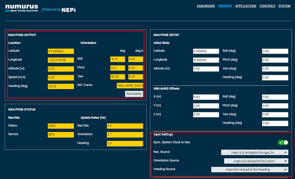
RBX Settings and Status Interface
All RBX drivers support a settings and status messages for the RBX state, mode, ready, goto error data, and other configurable parameters.
For now, we will focus on two RBX setting controls, set_mode and set_state, which are required to be set to “GUIDED” and “ARM” before we can take over the ardupilot control system and send control signals.
Example:
rostopic pub /nepi/s2x/ardupilot/rbx/set_mode std_msgs/UInt8 "data: 4"
rostopic pub /nepi/s2x/ardupilot/rbx/set_state std_msgs/UInt8 "data: 1"
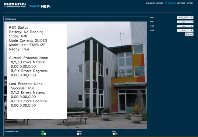
While you could monitor all of the RBX status information as text from a terminal, RBX drivers publish an image that overlays important status and process information on top of the robot’s main camera image stream, or a black image if no camera is available. This image is published on the RBX topic.
<Your NEPI Device Basename>/ardupilot/rbx/status_image
Example:
/nepi/s2x/ardupilot/rbx/status_image
You can view this status overlayed image using the NEPI Image Viewer Application, by opening the RUI APPLICATIONS/IMAGE VIEWER tab and selecting the “status_image” from one of the dropdown boxes.
Example:
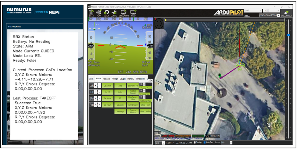
After entering the change mode and state commands above, we can see these updated on the published RBX status image below. The last mode is also shown. Since we have not sent any control commands, neither the current or last process sections show “None” next to the process name lines.
RBX Command Controls
All RBX drivers support a common set of ROS command control topics that provide actions and movements that are listed in the table below with a description for the ardupilot RBX interface.
Ardupilot RBX Command Controls
| Control Topic Name | Description |
| <basename>/ardupilot/rbx/go_action | Integer value to supported action capabilities like “takeoff” |
| <basename>/ardupilot/rbx/go_home | Commands the control system to stop any current actions and change to “RTL” mode |
| <basename>/ardupilot/rbx/go_stop | Commands the control system to stop any current actions and change to “Loiter” mode |
| <basename>/ardupilot/rbx/goto_pose | Commands the control system to adjust pose angles to the provided Roll, Pitch, Yaw values in degrees* |
| <basename>/ardupilot/rbx/goto_position | Commands the control system to a new body relative x,y,z position in meters. |
| <basename>/ardupilot/rbx/goto_location | Commands the control system to move to a new GPS coordinate location, altitude in meters, and yaw angle in degrees* |
* A value of “-999” entered for any input will use the current NavPose value and not include that input’s current value in any translational or angle error adjustments.
NOTE: Only the “go_stop” and “go_home” command can be initiated while another command control process is active. The other control processes will ignore the control message.
NOTE: Only the “go_stop” and “go_home” command can be initiated while another command control process is active. The other control processes will ignore the control message.
Setting Command Control Error Goals
RBX command controls try to achieve the “goto” command control values to with the values set in the “goto_goals” values which include three parameters: translation abs error bound in meters, angular absolute error bound in degrees, and a stabilization time in seconds for each of the values provided in the command.
Monitoring Command Control Processes
There are two ways we can monitor progress of an initiated command control.
1) The status “ready” topic returns a True when there is no active command control processes, or False when there is an active command control process.
2) The status “goto_errors” topic returns a list of errors [x meters, y meters, z meters, roll degrees, pitch degrees, yaw degrees] for an active command control process, except the “go_stop” and “go_home” commands which rely on the ardupilots built in “Loiter” and “RTL” modes to perform the action. Errors are set to zero when no active command control is in process.
3) The RBX “cmd_success” topic provides information about the success of the last command control that was executed and completed.
NOTE: GoTo command control processes will continue to try and reach the set “goto” input values until either they are reached to within the error bounds set by the RBX “goto_goals” parameters, or process times out by reaching the value set in the RBS “timeout” value since the process was initiated.
In practice these monitoring parameters are used to wait for the system to be in a “ready” state before sending a “goto” command, wait for the “goto” command to start and complete, then check the success of the command.
Example:
Code snippet from the “drone_waypoint_demo_mission_script.py” automation script demonstrated later in this document.
### Function to call goto location command control
def goto_rbx_location(goto_data):
global rbx_status_cmd_success
global rbx_goto_location_pub
# Send goto Location Command
ready = wait_for_rbx_status_ready()
print("Starting goto Location Global Process")
goto_location_msg = create_goto_message(goto_data)
rbx_goto_location_pub.publish(goto_location_msg)
ready = wait_for_rbx_status_busy()
ready = wait_for_rbx_status_ready()
return rbx_status_cmd_success
Command Control Example
Below is a simple RBX command control mission executed manually in an SSH terminal:
We have already set the ardupilot control system to “Guided” mode and “Arm” state in the last section, but before we can send any of the “goto” commands to control the robot’s movements, the ardupilot must be given a “takeoff” action command and reach the set height. The RBX ardupilot driver has this value hard coded to 10 meters.
NOTE: If the vehicle has already taken off and active when we want to take control, such as reacting to some AI detection during a normal waypoint mission, the “takeoff” command step below can be ignored.
1) Send “takeoff” command if not taken off yet.
rostopic pub /nepi/s2x/ardupilot/rbx/go_action std_msgs/UInt8 "data: 0"
2) Send RBX ardupilot “goto_location” action command to move to latitude 47.6541208, longitude -122.318662, altitude 20 meters using the current yaw value by setting its controls input to “-999”.
rostopic pub /nepi/s2x/ardupilot/rbx/goto_location std_msgs/Float64MultiArray "layout:dim: []data_offset: 0data: [47.6541208, -122.318662, 10.0, -999.0]"
3) Return to home location that was set when the system was armed.
rostopic pub /nepi/s2x/ardupilot/rbx/go_home std_msgs/Empty "{}"
Mission Automation
We can automate all the RBX processes discussed in this document using NEPI’s built-in Automation application and the automation scripts described in the table below.
NOTE: See the NEPI Engine tutorial on using the NEPI’s built-in Automation application for installing and running NEPI automation scripts available at: https://nepi.com/nepi-tutorials/nepi-engine-automation/
NOTE: The automation scripts used in this section are available for download from the NEPI sample automation scripts GitHub repo at: https://github.com/numurus-nepi/nepi_sample_auto_scripts
These particular scripts, along with the ardupilot configuration file used in this section are also available as a single zipped package downloadable from: https://www.dropbox.com/scl/fo/0v4geo9n7pn25zvgeyppb/h?rlkey=ix089itzrai1huruv27dvutuy&dl=0
Ardupilot Mission Automation Example Scripts
| Script Name | Description |
| _drone_waypoint_demo_startup_script.py | Starts all of the scripts listed below for convenience. |
| ardupilot_rbx_fake_gps_config_script.py | NEPI RBX fake gps process |
| ardupilot_rbx_driver_script.py | NEPI RBX driver interface |
| ardupilot_rbx_navpose_config_script.py | Configures the NEPI NavPose solution to use the ardupilot produced GPS, orientation, and heading data. |
| drone_waypoint_demo_mission_script.py | Runs a complete ardupilot mission including setting modes and state, taking off, moving to a set lat, long, altitude, then returning home. |
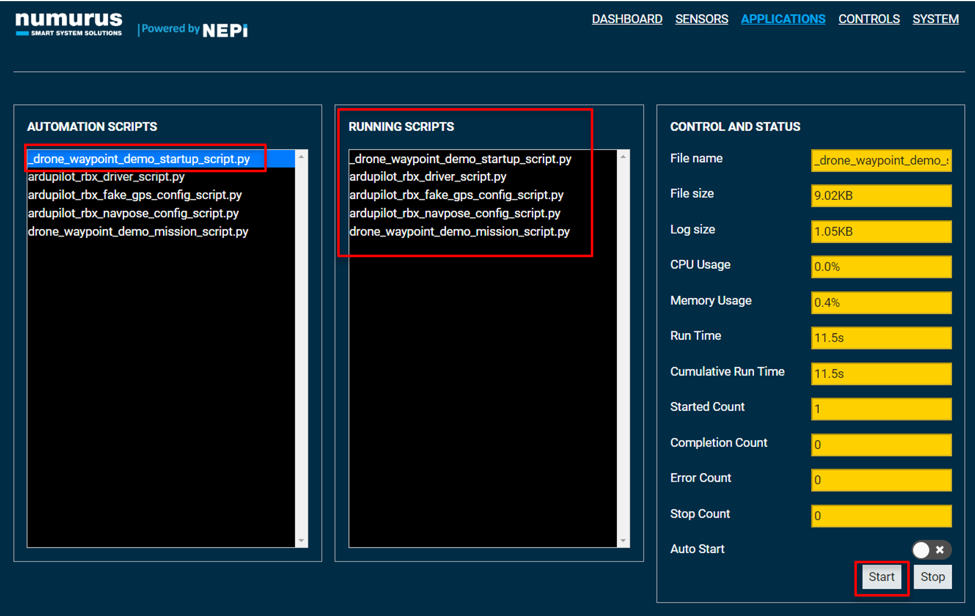
1) Open the NEPI device’s RUI APPLICATIONS/AUTOMATION tab, select the “_drone_waypoint_demo_startup_script.py” automaton script from the left pane, and click the “Start” button at the bottom left of the page. You should see this script and then the remaining scripts start up.
2) Open the NEPI device’s RUI APPLICATIONS/IMAGE VIEWER tab and select the “status_image” from one of the dropdown boxes to monitor the RBX mission processes, then open the Ardupilot Mission Planner software to monitor your ardupilot system simultaneously in real time.
