NEPI Engine – Software Manual
Introduction
NEPI Engine is a full-featured software platform for embedded AI-enabled processing hardware. NEPI installs on top of the base operating system and software provided by edge-compute board and chip manufacturers creating a feature-rich environment for edge-AI and automation development.
NEPI helps both new and experienced developers bypass many hurdles associated with bringing up and creating edge-AI enabled solutions. With a library of plug-and-play abstracted hardware drivers, robotic control system interfaces, drag-and-drop AI and automation applications, and customizable browser-based user interfaces, NEPI lets smart system developers focus on their end- solution, not building low-level software.
Software Features
![]()
AI and Automation Applications
To enable the rapid development and deployment of advanced AI-enabled automation solutions, NEPI includes a suite of integrated applications that support drag-and-drop deployment and orchestration of AI models and automation scripts.
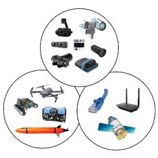
Abstracted Hardware Drivers
One of the key benefits of the NEPI software system are abstracted sensors, actuators, communications, robotic hardware interfaces provided by a library of interface drivers that allow plug-and-play operation with industry standard hardware components.
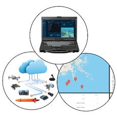
Browser-Based User Interfaces
As most edge processing solutions do not include attached keyboards, mice, and displays, NEPI provides a customizable browser-based resident user interface (RUI) system hosted on-board the device.
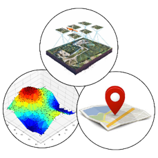
Onboard Data Management
NEPI supports sophisticated onboard data logging of synchronized image, point clouds, navigation, pose, and other data types that are typically required at some point for any AI and mobile robotics automation project.
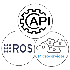
API Programing Interfaces
NEPI supports a variety of programmatic interfaces for applications to use including Native ROS, WebSocket API, Native video servers for direct access to low latency imagery data.
PC Side Setup
The initial connection to your NEPI device is made through a wired Ethernet connection using the instruction below.
NOTE: Once you have successfully connected and logged into your systems RUI interface, you can enable the systems WiFi access point option for WiFi enabled hardware, then connect through WiFi rather than Ethernet if that method is more convenient. See “Creating a WiFi Access Point” for instructions on setting up a WiFi access point for your NEPI device.
PC Network Adapter Setup
1) Connect an ethernet cable from your NEPI-enabled hardware to a local LAN, switch, or directly to a PC.
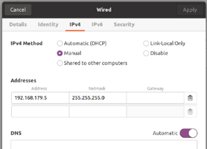
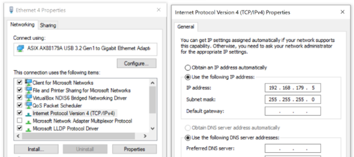
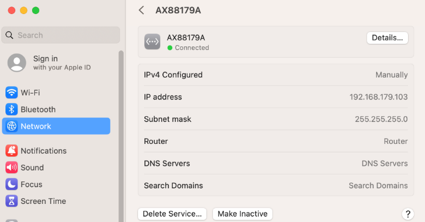
YOU WILL NEED TO ENSURE THAT THE HOST COMPUTER’S ETHERNET INTERFACE IS CONFIGURED WITH A STATIC IPV4 ADDRESS ON THE 192.168.179.0/24 SUBNETWORK. FOR EXAMPLE: IP Address: 192.168.179.5 Netmask: 255.255.255.0
Network Adapter Setup (Linux)
Network Adapter Setup (Windows)
Network Adapter Setup (Mac)
For a detailed overview of this and other PC side setup procedures, see the NEPI Engine – Getting Started tutorials at:
https://nepi.com/tutorials/
Accessing NEPI’s Resident User Interface (RUI)
The NEPI’s Resident User Interface (RUI) provides a browser-based user interface for configuring, validating and monitoring activities. The NEPI RUI is comprised of a top-level menu with additional submenus appearing under each top menu item.
A network-connected NEPI-enabled device’s RUI is accessed through a network connected PC, tablet, or smartphone by entering the NEPI device’s fixed address http://192.168.179.103:5003 (or at any other custom IP address configured on the device).
Recommended Browser: Google Chrome or Microsoft Edge (Firefox has feature limitations that severely limit RUI usability)
Connecting to the RUI (All Devices)
1) Power your NEPI-enabled hardware platform and allow 30-60 seconds for the system to boot.
2) On the computer attached to the NEPI via the ethernet connection, open a Chrome web browser and navigate to the URL: http://192.168.179.103:5003.
a) The NEPI RUI application will initiate and display system dashboard tab.

You will also want to disable any drivers, applications, or AI models you don’t need to optimize system performance.


To learn more about getting started, see the NEPI Engine – Getting Started tutorials at: https://nepi.com/tutorials/
Accessing NEPI’s User Storage Drive
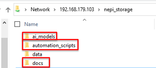
NEPI’s onboard user storage drive is where users can manage their data, AI models, automation scripts, databases, software configuration, and more. The user storage drive is factory configured with the following factory folders:
NEPI User Storage Folders and Descriptions
| Folder Name | Use Description |
| ai_models | AI image detection model library |
| automation_scripts | Automation script library |
| data | Onboard logged data folder |
| docs | Manuals and API documentation |
| license | System license files and license request |
| logs | System generated logs are stored |
| nepi_full_img | Install (upgrading) system image files |
| nepi_full_img_archive | Archived (backup) system image files |
| sample_data | Data (images, videos, pointclouds…) used for testing and demonstrations |
| user_cfg | User and system configuration files |
The user storage drive is made available as a shared network drive (i.e., Samba server) with the following default credentials:
– IP Address: 192.168.179.103\nepi_storage
– Username: nepi
– Password: nepi
Connecting to the User Storage Drive (Linux)
From the File Navigator, select + Other Locations. Enter the device URL as shown in the screenshot below, ensuring that you preface with smb:// (e.g., smb://192.168.179.103/)and substituting a different IP address if your device is configured with an IP address different than the default value. You will be presented with a login screen and need to provide the credentials as indicated above. After entering credentials, you should see the subdirectories listed above. You can drag/drop, copy/paste locally, or delete files.
Connecting to the User Storage Drive (Windows)
Enter the system IP address and data folder in your file explorer window’s address bar (e.g., \\192.168.179.103\nepi_storage). You will be prompted for a username and password. After entering credentials, you should see the subdirectories listed above. You can drag/drop, copy/paste locally, or delete files.
Connecting to the User Storage Drive (Mac)
Open the Finder application and select the Network open on the left access bar. You should see you NEPI device listed. Click on the NEPI device and enter the username and password provided at the beginning of this section.
To learn more about using the NEPI User Storage Drive, see the NEPI Engine – Getting Started tutorials at: https://nepi.com/tutorials/
Accessing NEPI’s ROS Interface
NEPI leverages the Robot Operating System (ROS) toolset extensively. The information provided in this section provides information for accessing the NEPI ROS environment. To learn more about ROS you can find a significant amount of information online by searching for ROS in any web-browser. Here is a good place to start: http://wiki.ros.org/ROS/StartGuide.
To learn how to setup a PC with ROS and configure it to communicate with the NEPI ROS environment, see the tutorial “Setup Host PC for NEPI ROS Env” at: www.nepi.com/documentation.
Accessing NEPI’s File System
While NEPI provides extensive system and application support through its Resident User Interface and Data Storage Drive solutions. There are times when you may need access to the NEPI file system and codebase. These include debugging system issues, command line testing of automation scripts, and NEPI customization development. The NEPI file system is accessed from a network connected PC using a Secure Shell (SSH) terminal connection to the NEPI device.
To learn how to setup a PC, connect, and customize to the NEPI file system, see the tutorial “Accessing and Configuring NEPI File System” at: www.nepi.com/documentation.
Accessing NEPI’s Desktop Interface
As most NEPI software applications are intended for embedded systems, there are only a few reasons you might need to connect to your NEPI device using a conventional desktop setup (mouse, keyboard, display connected directly to the NEPI device). The two main reasons would be:
a) Debugging a network communications issue
b) Developing a desktop interface solution that requires direct display and input connections.
The following instructions assume your NEPI device has both an HDMI display port and USB ports.
Instructions
a) Connect an HDMI display, USB keyboard, and USB mouse to your NEPI device
b) Power on your NEPI device
c) At the login screen, select the “nepi” username. Enter “nepi” for default password
d) The desktop should come up and look like this:
e) Access the NEPI RUI interface from the NEPI desktop by opening the system’s web-browser and either selecting the preset “RUI App” link from the favorites bar, or entering “localhost:5003” in the address bar.
NEPI Device-Side Setup
Ethernet, WiFi, and Access Point Setup
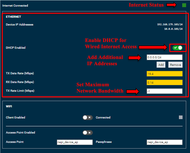
NEPI comes configured with a factory set Base Ethernet Address (192.168.179.103) that makes setup and connecting to a local laptop easy since this address is always available. The following Ethernet configuration options are made available through the RUI SYSTEM/ADMIN tab.
Enabling DHCP
If you plan to connect to the internet through an internet connected LAN or modem, you will need either to specific a static IP address on the LAN subnet or turn on DHCP client support first by selecting the DHCP Enabled switch. With DHCP client support enabled, a new DHCP-assigned IP address will appear in the IP address list once the NEPI device is assigned one by the DHCP server on the LAN.
Adding Ethernet IP Addresses
You can add additional IP address aliases to the system’s factory base IP address (192.168.179.103) that make it easy to integrate a NEPI-enabled device into an existing local area network (LAN). The IP address uses standard CIDR notation, with the subnet indicated by a “/” and subnet mask bit count (/24 is shorthand for 255.255.255.0, /16 is shorthand for 255.255.0.0, etc.). You can set the maximum streaming bandwidth by entering a maximum bandwidth value in Mbps and hitting enter, or disabling bandwidth limiting by entering a “-1”. Bandwidth limiting only affects outbound data packets on a LAN system, and typically results in reduced data/image update rates. It does not affect internal communications within the NEPI-enabled device such as data logging or inter-process communication.
WiFi Setup
NEPI supports configuring connected WiFi hardware for simultaneous internet access and a local system access point. Some WiFi hardware adapters may not support simultaneous configurations, in which case you will only be able to set one of these options. The following WiFi configuration options are made available through the RUI SYSTEM/ADMIN tab. The WiFi setup pane is only visible if the NEPI device detects a compatible WiFi adapter. If you do not see this setup pane in the RUI, then your device has not auto-detected the WiFi hardware.
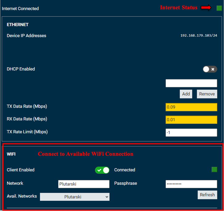
Connecting to Available WiFi Network
If your NEPI-enabled device needs access to a WiFi network, usually for internet connected IoT applications or remote access to the device or RUI, first, select the Client Enabled switch if disabled, refresh the Avail Networks list (if necessary), select the network you want to connect to from the list, enter the access passphrase and press <Enter>. You should see a green indicator showing the device is connected.
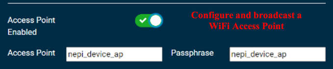
Creating a WiFi Access Point
If you want to setup a WiFi access point giving RUI and SSH access to local WiFi enabled phones and PC’s, or other NEPI-enabled devices, first, select the Access Point Enabled switch if disabled, then input a name and passphrase for your WiFi access point. Test that the access point is working by searching for available WiFi networks on a local phone or PC, select the NEPI network and use your passphrase to connect to it. You should be able to reach your devices RUI over this WiFi connection by opening a web browser on the phone or PC and entering: http://192.168.179.103:5003.
Clock Synchronization
In many applications, it is important to synchronize to an available system time clock and synchronize your NEPI-enabled device with this system clock available on a connected piece of hardware (PC, INS, sensor, etc.). This is particularly true for NEPI devices that do not include a battery-backed clock, since these devices boot up with a static, necessarily incorrect timestamp.
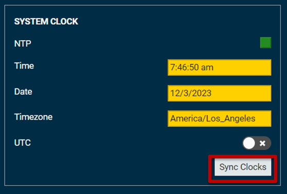
RUI Time Syncing
NEPI provides an alternative, yet less accurate time syncing solution through the NEPI RUI graphical user interface using an html-based sync solution. Connect to your NEPI’s RUI Dashboard tab from the time reference’s source computer (your laptop) in a web browser and select the “Sync Clock” button on the dashboard.
NTP Server Time Syncing
By default, NEPI looks for and will connect to a local NTP server broadcasting on IP address 192.168.179.5. Additional NTP server IP addresses can be added by publishing the IP address to the ROS topic “add_ntp_server”. For more information on configuring and connecting an local NTP server with your NEPI device, see the tutorial “Configuring NTP Time Syncing” available at:
ROS Message Time Syncing
The NEPI system clock can be updated by sending a ROS “std_msgs/Time” message to the ROS topic “set_time”. This method of time synchronization has the most latency of the three options.
NEPI Hardware Interfacing
Imaging Sensors
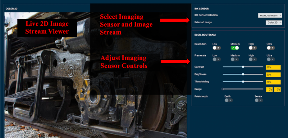
NEPI supports plug-and-play interfacing with 2D and 3D imaging sensors (cameras, lasers, sonar…) through its IDX abstracted image sensor driver system, which maps image sensor data and controls to standardized IDX interfaces. The IDX interface lets downstream AI and automation applications work with and IDX connected sensor without any process changes.
The instructions below explain how to use the RUI’s IDX SENSOR tab to view and configure IDX connector imaging sensors:
1) Connect your IDX supported imaging sensor(s) to your NEPI-enabled device through an appropriate port.
NOTE: If your device is ethernet based, you must ensure that your NEPI device and sensor have compatible IP addresses. You can either configure your NEPI device or your sensor IP address to be on the same IP subnet as the other.
2) Select the sensor from the IDX Sensor Selection drop down list and select the sensor’s image stream of interest from the Selected Image drop down list. You should see your selected sensor/image stream live in the 2D image window, along with the image name above it.
3) Adjust any of the imaging sensor’s controls and see changes in real-time. Only those controls that are available for that particular sensor will be changeable – others will be disabled.
4) If you want your control changes for that imaging sensor to persist after reboot, you must navigate to the RUI SYSTEM/ADMIN tab and select the “SAVE ALL” button.
Light and Strobe Devices
NEPI supports connecting and managing lighting and strobe devices through NEPI LSX abstracted lighting and strobe interface. The following instructions provide an overview of how to connect and manage a NEPI LSX supported device. The NEPI LSX interface provides the current device status of lighting or strobe device, along with standard settings and controls.
The instructions below explain how to use the RUI’s LIGHTING tab to monitor and control LSX support lighting and strobe systems.
1) Connect your LSX supported light or strobe device to your NEPI-enabled device through an appropriate port. The LSX driver will autodetect the device and make it available within your NEPI software environment.
2) Open a web-browser and navigate to the NEPI-enabled device’s RUI CONTROLS/LIGHTS tab.
3) Select the light or strobe device from the Lighting Device selection drop down list. You should see state information and other available feedback in the data boxes below that selection.
4) Select a connected camera/image placed on the pan & tilt system you would like to view live in this window from the Image Sensor/Image Topic dropdown box. You should see your selected sensor/image stream live in the 2D image window, along with the image name above it.
5) Adjust any of the device’s supported controls and see changes in real-time, along with live image updates.

Pan and Tilt Actuators
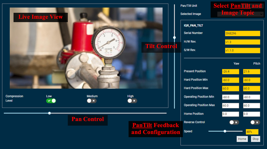
NEPI supports connecting and managing pan and tilt actuators through NEPI PTX abstracted pan and tilt interface. The following instructions provide an overview of how to connect and manage a NEPI PTX supported pan and tilt device. The NEPI PTX interface provides current position and status of the pan/tilt device, along with standard settings and controls.
The instructions below explain how to use the RUI’s PAN_TILT tab to monitor and control PTX support pan and tilt systems.
1) Connect your PTX supported pan and tilt device to your NEPI-enabled device through an appropriate port.
NOTE: If your device is ethernet based, you must either configure your NEPI-device’s or your system’s IP address to be on the same IP subnet.
2) Open a web-browser and navigate to the NEPI-enabled device’s RUI CONTROLS/PAN&TILT tab.
3) Select the pan and tilt device from the PTX Device Selection drop down list. You should see state information and other available feedback in the data boxes below that selection.
4) Select a connected camera/image placed on the pan & tilt system you would like to view live in this window from the Image Sensor/Image Topic dropdown box. You should see your selected sensor/image stream live in the 2D image window, along with the image name above it.
5) Adjust any of the pan and tilt controls and see changes in real-time, along with live image updates as you move your pan and tilt.
6) If you want your control changes for that pan & tilt system to persist after reboot, you must navigate to the RUI SYSTEM/ADMIN tab and in the Configuration pane select the specific pan/tilt unit or “ALL” before pressing the “Save” button.
Navigation and Pose Sensors
NEPI supports plug-and-play interfacing with external navigation and attitude sensors (GPS, IMU, INS…) through its NPX abstracted NavPose driver system, which maps NavPose data to standardized NDX interfaces and file formats and publishes its NavPose solution for other NEPI applications to use.
NEPI NavPose Conventions
NEPI uses a north-east-down (NED) global reference frame and a forward-right-down (FRD) local body reference frame as defined below.
NED Global Frame: X is North, Y is East, Z is Down (Towards Earth Center), and Yaw 0 degrees faces North and rotates positive using right hand rule around Z axis down.
Local Body Frame (Fixed to Robotic Platform Body): X axis points in Forward (defined by geometry and not by movement) direction (RHR roll axis), Y axis points to the Left (geometrically) (RHR pitch axis), Z axis points Up (geometrically) (RHR yaw axis), Yaw 0 degrees faces X and rotates positive using right hand rule around Z axis down.

For Altitude NEPI uses WSG84. For Depth, NEPI assumes depth below sea level.
RUI NavPose Configuration and Monitoring
The RUI Sensors / NavPose tab provides a graphical interface for configuration and monitoring your systems NavPose solution.
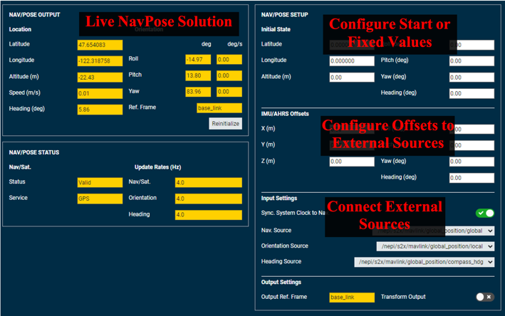
Configuring Fixed Asset Data
For applications involving fixed assets, NEPI supports direct entry of location, heading, and/or pose data.
The instructions below explain how to use the RUI NAVPOSE tab to manually enter and save fixed location, heading, and/or pose data.
1) Open the RUI SENSORS/NAVPOSE tab and edit the NAV/POSE Setup – Initial State entry boxes with the values of your fixed asset.
2) You can press the “Reinitialize” button on Nav/Pose Output pane to see your updates take effect but note that they will be immediately overridden by any live updates streaming in on the topics selected in the “Input Settings” pane.
3) Go to the RUI System/Settings tab and in the Configuration pane, select either “Nav/Pose/GPS” or “All” from the dropdown before pressing the “Save” button.
Configuring External IMU/INS Input Data
All offsets should be applied positive or negative depending on which direction you are moving in the pipeline relative to the data. For instance, sensor data moving to a common reference frame should be negative measured from the device frame of reference, while external frame of references should be positive measured from the device frame of reference. The transform values must be calculated based on the following directions and order of transformation:
1) First Sync INS and NEPI clocks using external NTP Server
2) Open the RUI SENSORS/NAVPOSE tab and select the appropriate data sources from the dropdown boxes in the NavPose Input Settings section
3) Apply any transforms required using the following conventions:
4) Transforms are positive FROM the Device Frame of Reference TO the External INS Frame of Reference
5) Transformation order is X, Y, then Z in meters
6) Rotation order is ∆X, then ∆Y, then ∆Z in degrees (right-handed rotations) where the rotation axes are fixed to DFoR throughout the rotation sequence
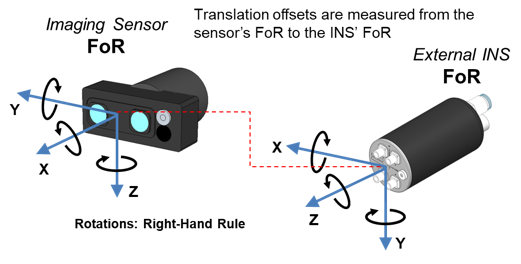
For the example above, the correct offsets for this configuration as measured from the Sensor to INS Offsets are: X= –0.25, Y= 0.007, Z= 0.152 ∆X=90.0, ∆Y=0.0, ∆Z=90.0
To learn more about configuring your NEPI NavPose solution, see the NEPI Engine – Hardware Interfacing tutorials at: www.nepi.com/tutorials.
NEPI Built-In Applications
IMAGE VIEWER Application
NEPI’s Image Viewer application provides an interface for monitoring up to four live image streams simultaneously. The live image viewer windows will populate and resize dynamically based on your selected image topics from the dropdown boxes. Any image data including raw sensor streams, AI detection output images, and custom automation processed image streams are available for selection.
The instructions below explain how to use the RUI’s IMAGE VIEWER tab to monitor available system image streams.
1) Open a web-browser and navigate to the NEPI-enabled device’s RUI APPLICATIONS/IMAGE VIEWER tab.
2) Select up to four image streams to display.
3) The Snapshot button produces a system wide “snapshot event trigger” only. Snapshot actions are controlled through NEPI automation scripts. In order to take some action based on a snapshot event trigger, you must have at least one “snapshot event action” automation script running.
To learn more about implementing snapshot event actions, see the NEPI Engine – Using and Creating NEPI Automation Scripts tutorial at: https://nepi.com/documentation/. 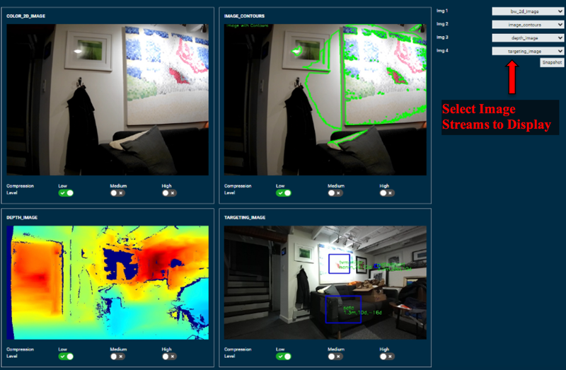
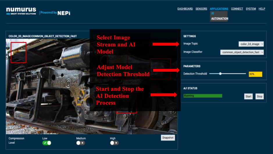
AI Application
NEPI’s AI application provides a framework for storing, configuring, and running user AI models from NEPI’s User Storage “ai_models” folder. The AI application manages which of the available AI models is active at a given time, which sensor stream(s) input to the active model, and any additional parameters related to AI model execution. The AI application also supports external AI process orchestration such as active model selection and on-the-fly data input switching. The AI application supports AI inference output logging of labeled images and text-based bounding box descriptions and ensures AI model outputs adhere to a standard ROS 2D label topic format, ensuring a consistent interface for both on-board and off-board consumers of the AI output data streams.
The instructions below explain how to use the RUI’s AI tab to setup, start, and monitor AI detection processes for your systems.
1) Open a web-browser and navigate to the NEPI-enabled device’s RUI APPLICATIONS/IMAGE VIEWER tab.
2) Select up to four image streams to display.
3) The Snapshot button produces a system wide “snapshot event trigger” only. Snapshot actions are controlled through NEPI automation scripts. In order to take some action based on a snapshot event trigger, you must have at least one “snapshot event action” automation script running.
4) While you can save the current AI setup so it starts automatically on startup by saving user settings in the RUI’s SYSTEM/ADMIN page, best practice is to manage AI process with NEPI automation scripts.
To learn more about orchestrating deployed AI detection models, see the NEPI Engine – Application tutorials at: www.nepi.com/tutorials.
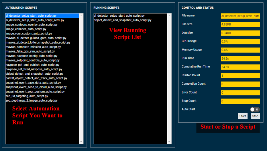
AUTOMATION Application
NEPI’s Automation application provides a framework for storing, configuring, and running user automation scripts/executables from NEPI’s User Storage “automation_scripts” folder. The automation application manages which of the available automation scripts is active at a given time. User automation scripts leverage both the Linux system API and NEPI API to create actions based on system data and AI outputs. Actions may include any number of items including but not limited to saving data on board, adjusting sensor and AI model orchestration, and sending information to a remote cloud server.
NOTE: You can download example NEPI automation scripts from the NEPI Engine automation script GitHub repo at: https://github.com/numurus-nepi/nepi_sample_auto_scripts.
The instructions below explain how to use the RUI’s AUTOMATION tab to start, stop, and monitor automation scripts installed on your system.
1) Connect to the system’s RUI APPLICATIONS/AUTOMATION tab. Select the automation script(s) you want to test then click the Start button.
2) Verify your automation script is working properly by checking the RUNNING SCRIPTS window on this UI tab. You can also observe statistics about the selected script in the CONTROL AND STATUS window.
NOTE: If you want to see live print statement outputs and process error messages, you will need to run the automation script in an SSH connected terminal from the “/mnt/nepi_storage/automation_scripts/” folder.
To learn more about orchestrating deployed automation scripts, see the NEPI Engine – Application tutorials at: www.nepi.com/tutorials.
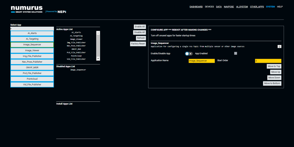
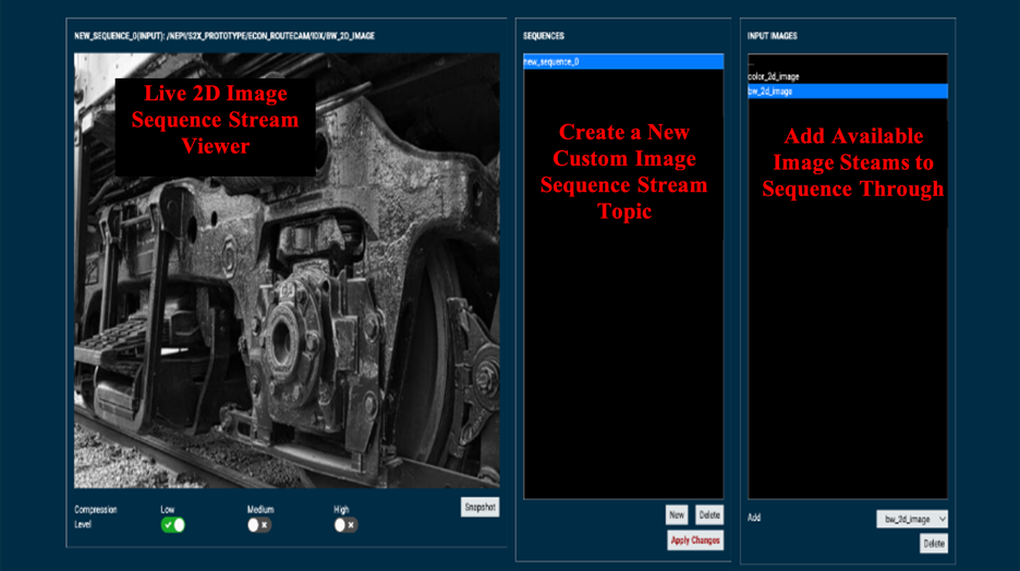
SEQUENCER Application
You can create custom sequenced image streams from multiple cameras and/or multiple image streams from a single camera. These sequenced streams are useful when wanting to feed multiple camera streams into a single AI model or automation script. Once created, custom sequenced image streams are available inputs in both the NEPI AI and Automation Applications
The instructions below explain how to use the RUI’s SEQUENCER tab to create sequenced image streams from multiple cameras:
1) Open a web-browser navigate to the NEPI-enabled device’s RUI APPLICATIONS/SEQUENCER tab.
2) Select the NEW button under the SEQUENCER topic box and create a new custom image sequence stream topic.
3) Select available image streams in the drop-down menu under the INPUT IMAGES box or DELETE image stream topics already added to the sequence list. You should see the sequenced images cycle through in the 2D image box on the right.
4) If you want your image sequence stream topic to persist after reboot, you must navigate to the RUI SYSTEM/ADMIN tab and in the Configuration pane select either “Sequencer” or “ALL” from the dropdown before pressing the “Save” button.
To learn more about orchestrating sequenced image streams, see the NEPI Engine – Application tutorials at: www.nepi.com/tutorials.
NEPI Software Management Tools
User and System Settings
NEPI includes a large set of user-configurable parameters, which can be modified with or without saving the changes as defaults for future sessions. Each system ships with a factory configuration and the ability for users to restore the system to factory defaults both at the individual module level and for all modules globally. User modifications from the factory settings are stored in separate user configuration files.
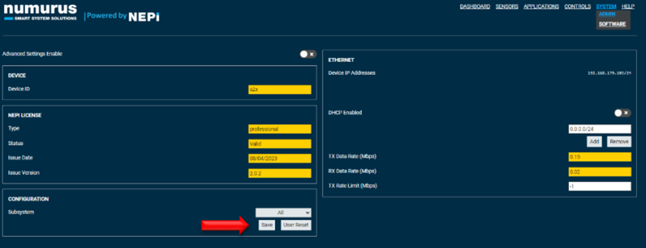
Saving Configuration Settings
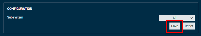
The RUI provides sophisticated graphical configuration in a convenient web-browser application. Many of the configurable parameters in the system are exposed through the various tabs of the RUI, providing end users a complete system configuration capability. To save system settings so that they persist after reboot, you must explicitly save it via the RUI System/Admin page. If you want to save only settings associated with a particular subsystem, not any others you might have adjusted, select that subsystem from the Subsystem drop-down menu prior to pressing the “Save” button.
Configuration Settings via ROS
Many parameters of NEPI may be updated through the use of the ROS messages and services. For details on system setup, see “NEPI – Local System Interface_API” document at: https://nepi.com/documentation/.
Configuration Settings Manually
Many of the system level settings including serial number, base IP address, and more can be modified by editing the appropriate file in the user_settings/user_cfg/sys folder on the NEPI device’s network shared user drive.
NOTE: It is recommended that you back up any files before editing them, so that you can restore them in case something is not configured properly and you are not able to access your RUI.
For details on common system configuration changes and appropriate files to edit, see the section “Configuring the NEPI File System” in this document.
Restoring System Settings
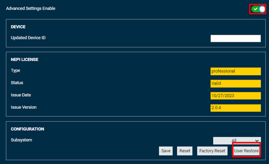
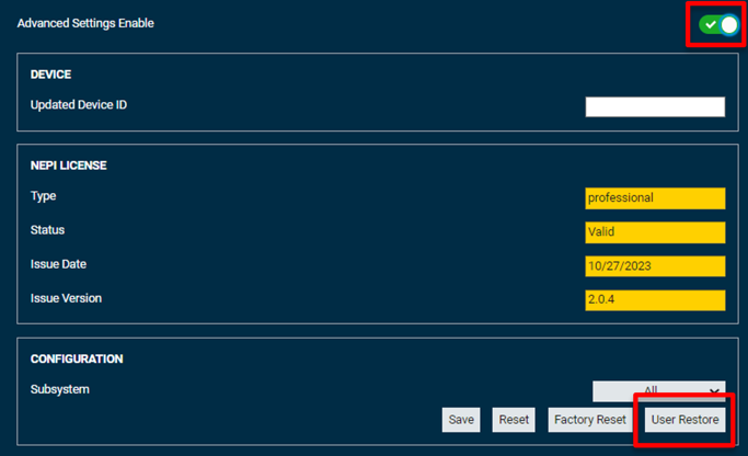
After software upgrades or manually editing system files, you must restore your saved settings from the “nepi_storage/user_cfg” folder back to the NEPI device’s file system by opening the RUI Settings/Admin tab, enabling the “Advanced Settings Enable” button, and selecting the “User Restore” button.
Reverting Current Changes
The User Reset button in the Configuration section of the Settings tab allows you to undo any changes you have made to the system since the last time settings were saved. This has the same effect on settings as power cycling the device with the benefit of taking immediate effect with no downtime. As with the Save button, this can be applied to all subsystems simultaneously or just a select subsystem via the Subsystem drop-down menu.
Reverting to Factory Settings
It is possible to completely revert a selected subsystem or the entire device back to Numurus factory settings. As this can undo considerable prior work, the Factory Reset button is only exposed when Advanced Settings Enable checkbox is selected.
Software Updating, Backup, and Cloning
NEPI includes a flexible system for updating, backing up, and cloning the NEPI software system. Typical steps for a complete system image updating are provided below. See the “Numurus_API_NEPI – File System” document for more details on how to create and manage NEPI software images.
Updating NEPI Software Image
1) Obtain the image file. Numurus maintains image files for a number leading edge-compute hardware platforms downloadable at: https://www.dropbox.com/scl/fo/xs08d4c43dupfg1ftc2vy/h?rlkey=we8r0omh123ufq9opbl5yj0g6&dl=0.
2) Ensure it has a filename of the form nepi_*_sys.img.raw, where the wildcard * can be any valid filename substring. If the file has a .zip extension, make sure to unzip the file first.
3) Copy the image to the nepi_full_img subdirectory from your development host system via networked filesystem access (Samba). 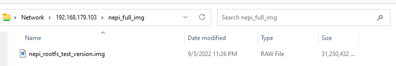
4) Save all your current system and user settings by selecting the “Save” button on the RUI’s System/Admin tab with “All” selected in the dropdown box.
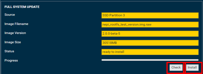
5) From RUI System/Software page in the Full System Update section, select Check. The image should be detected and the NEPI s/w version reported in the Image Version textbox. The Status text field should report “Ready to Install.” Click “Install” button to start the installation and wait for installation to complete.
5) Reboot your NEPI device.
6) Following successful install, the Active and Inactive definitions should be swapped so that on next reboot the new image will be the Active one. In rare cases, it may be necessary to manually click the Switch Active/Inactive button – the Full System Update: Status text field will inform you if that is the case.
7) Restore your saved pre-install system and user settings by opening the RUI Settings/Admin tab, enabling the “Advanced Settings Enable” button, and selecting the “User Restore” button.
8) (Optional) You can also update your system’s documentation, AI models, and automation scripts with the latest release by downloading the folders from the following link: https://www.dropbox.com/scl/fo/c7qap49hftrmi13ku49tg/h?rlkey=kbufq3lv04y9c2etc17kotk0j&dl=0.
Once downloaded, replace the folders on your NEPI devices user_storage network shared drive.
Software Backups and Cloning
If you are planning to make changes to your NEPI file system, or have an image that you want to deploy to other systems, you can quickly create a backup image of the current NEPI file system following these instructions:
NOTE: Backups can only be made on your NEPI device’s inactive partition. If you want to back up your active partition, first select the “Switch Active/Inactive” partition control, then reboot your system. It will now come up with the partition you want to clone as the inactive partition.
1) In the RUI’s SYSTEM/SOFTWARE tab, check that the partition you want to clone is listed in the “Source” box, then click the “Archive” button from the FULL SYSTEM ARCHIVE box.
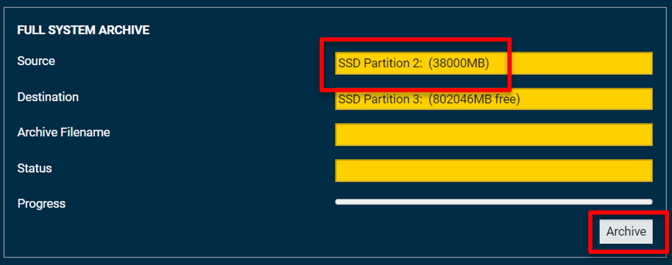
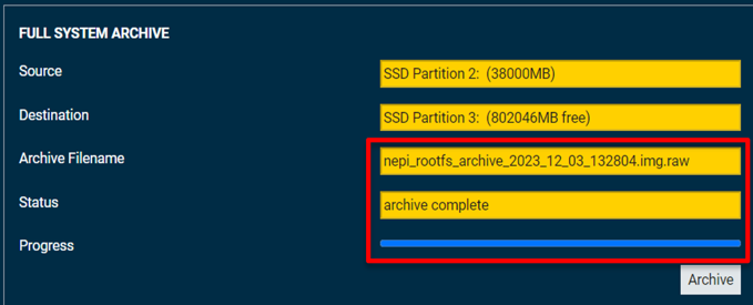
2) Monitor the image archiving process until complete.
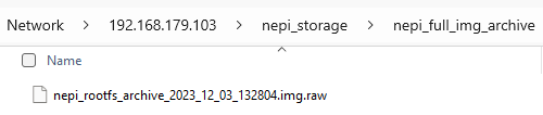
3) Copy your archived NEPI image from the NEPI Storage drive’s “nepi_full_img_archive” folder to your PC or wherever you want to store it. You can also rename this file ensuring it has a filename of the form nepi_*_sys.img.raw, where the wildcard * can be any valid filename substring.
NOTE: You can now use the archived NEPI image as a backup image to restore your current system’s image if corrupted, or copy and install on another system following the “Updating NEPI Software Image” instructions.
Software License Management
NEPI is available under either a Developer license or a Commercial license, providing a flexible solution for every stage of your project development. The NEPI Developers license provides free use of the complete NEPI package for developers, students, educators, and teachers. Users are only required to upgrade to a Commercial license when and if they want to deliver NEPI in a commercial product or service.
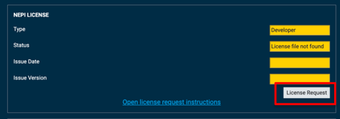
On startup, NEPI looks in the user shared partition on the NEPI system under nepi_storage/license folder. Commercial license files are unique for each device based on a device hardware identifier. If no license file is present or an invalid license file is detected, NEPI defaults to a Developer’s license. If there is a problem with an installed license file, details will be displayed on the SYSTEM/ADMIN RUI tab in the NEPI License section.
View NEPI Engine license options at:
https://nepi.com/software-nepi-engine/#License-NEPI-Engine
While NEPI file systems are the same for both Developer and Commercial licensed systems, Developer licensed installations will show a message “DEVELOPER VERSION: NOT FOR COMMERCIAL USE” along the header of any user interfaces. As shown below.

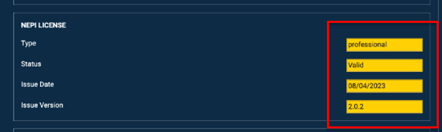
You can check the License type of a NEPI installation on the SYSTEM/ADMIN RUI tab under the “NEPI LICENSE” section as shown below.
Updating NEPI to Commercial License Version
Below are the steps to perform in order to request, purchase, and install a valid Commercial license on your system.
1) Click the “License Request” button in the SYSTEM/ADMIN RUI tab in the NEPI License section. This will create a unique license request file with your systems hardware and software details needed for Numurus to create a Commercial license file for your system.
2) Open the user shared partition on the NEPI system and navigate to the nepi_storage/license folder. Copy the license request file to your computer and email this file with a brief description of your request to nepi@numurus.com. Numurus will then send you a quote for a NEPI Basic Commercial license or use an available software seat on an existing Professional Commercial license order.
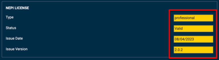
3) Once your order has been processed, Numurus will email you a unique license file for the device you produced the license request file from. Once you have that file, copy it to the user shared partition on the NEPI system at nepi_storage/license folder and check that your system registered the Commercial license file properly by checking the SYSTEM/ADMIN RUI tab in the NEPI License section on your system. If everything worked correctly, you should see one of the valid Commercial license types from the table above shown next to the license Type indicator and a “Valid” message next to the Status indicator on that tab.
NOTE: Each generated license file is unique to each device and the license file’s hardware identifier must match with the device’s hardware identifier for the system to accept received license as valid. The License file’s filename carries the hardware ID in it for easy verification.